
Abstract
The VEGA-3 laser system at the Centro de Láseres Pulsados delivers laser pulses up to 1 PW at 1 Hz repetition rate, focused to intensities up to  W cm−2. A versatile and compact solid target suitable for up to 0.05 Hz is presented which can operate in the challenging petawatt laser environment close to the laser-plasma interaction. Strips are spooled in a tape target system to deliver a solid density target to the laser focus for every shot. Results are presented for different tape materials and thicknesses, and a shot-to-shot standard deviation of the cut-off energy of 1.5% was obtained for Kapton reinforced aluminium tapes of 9 µm thickness. Experimental ion spectra are recorded by a Thomson Parabola Ion Spectrometer coupled with a scintillator screen; and an antenna array is used for the characterization of electromagnetic pulses. The results of both diagnostics show a good shot-to-shot stability of the system.
Export citation and abstract BibTeX RIS

Original content from this work may be used under the terms of the Creative Commons Attribution 4.0 license. Any further distribution of this work must maintain attribution to the author(s) and the title of the work, journal citation and DOI.
1. Introduction
The technological progress that followed the invention of lasers [1, 2] led to the present availability of many short-pulse PW-class Ti:Sa laser systems [3–8] that can operate at a high repetition rate. When tightly focused on matter, the relativistic interaction regime opens up to laser-driven sources of charged-particle beams [9], neutrons [10] and x-rays [11]. Pulsed bright ion beams are generated from solid-density targets by well known mechanisms such as target normal sheath acceleration (TNSA), radiation pressure acceleration (RPA) and others [12]. Many applications in Science and Technology benefit from laser-driven ion beams such as isotope production [13], positron emission tomography [14], ion beam microscopy [15], particle-induced x-ray emission [16] as well as inertial confinement fusion [17].
At present, the most important technical challenge of laser-driven sources is the repetition rate, as many difficulties arise when solid density targets are destroyed by laser and have to be replaced. A high-repetition-rate (HRR) operation  Hz is a major requirement for most of the above mentioned applications, which demands for HRR targetry solutions. Nowadays several approaches are pursued, e.g. generation of cryogenic ribbons [18], use of liquid jets [19, 20] or unwinding of a thin tape near the interaction position [21–32]. All of these schemes provide fast refreshing of target surface automatically and are able to deliver tens of thousands of targets in continuous operation under high-vacuum conditions. Tape targets stand out for their good vacuum compatibility and their flexibility regarding the material. Common problems of tape systems comprise their sensibility to laser-generated electromagnetic pulses (EMP), their mechanical stability and a large production of debris—all of which impeached a previous use of tape targets at HRR in the focus of PW-class lasers.
This study presents the Tape Target System (TaTaS-PW) for PW-operation, developed at the Centro de Laseres PUlsados (CLPU). It is based on a previous iteration of the system operational up to 150 TW [33]. We overcome limitations of mechanical stability posed by large ablation craters in the tape and further mitigate destructive EMP by an improved grounding. In addition we present studies comparing different tape materials and differently structured tapes. The paper is organized as follows: first the experimental setup and methodology are presented. Secondly, experimental findings from HRR tape targets and individually aligned tape-like targets are compared. Thirdly, future steps towards elevated repetition rates are discussed. Finally, we conclude and comment on future experimental applications.
2. Apparatus and methods
The tape target system TaTaS-PW is illustrated in figure 1. Spooling between laser shots, it transports several µm thick solid-density stripes of several mm width across the laser focal plane. The main frame of the TaTaS-PW system is made of a block of aluminum that incorporates (i) two shafts that house the tape spooling system, and (ii) two plastic teeth from PEEK that face each other across the laser-particle-plane and hold metallic pins which guide the tape over the laser focus plane.
- (i)The spooling system comprises one spool propelled by a stepper motor Phytron VSS42 which pulls the tape from the other spool connected to a braking system of 2.5 N cm to keep the tape taut. Both spools are from dielectric material to isolate tape and main frame. In addition, the motor is isolated from the main frame to avoid destructive strong currents towards the motor controller unit PolluxBox (PImicos), e.g. triggered by photo-ionization or stopped relativistic electrons on the main frame.
- (ii)The pins at a horizontal distance of
 mm ensure the tape stays in the laser-focus plane. The stability of the tape position normal to its surface is listed for different tape materials in table 1.

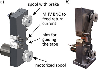
Figure 1. Tape target system for petawatt shots at VEGA-3: (a) technical details in the
Download figure:
Standard image High-resolution imageTable 1. RMS fluctuations of the tape target position normal to its surface, relative to the initially aligned focal spot position. Also given are the projections into the longitudinal direction relative to the laser (negative signs correspond to shifts towards the focusing parabola).
| Tape | Stable plane of tape (normal)/(µm) | Projection (laser)/(µm) |
|---|---|---|
| Al |

|

|
| Kapton (89-K-l-ad) |

|

|
| Kapton-enforced Al (9-Al-e-K) |

|

|
The relative positions are determined with a motorized microscope resolving steps on the order of several µm. As can be seen in table 1, the root-mean-square (RMS) deviation of the surface positions are much smaller than the Rayleigh length of VEGA-3, which is estimated to be ≈130 µm by beam diameter and focal length of the parabola. The small fluctuations of tape 89-K-l-ad can be explained by the glue layer which holds the tape tight, both other tapes are only held by the break. Further improvement of the braking mechanism will allow use of the system also for experiments with short focal parabolas.
Choosing PEEK as material for the mounting structures of the pins ensures the isolation of the tape from the main frame. The pins can be grounded to any point via MHV-BNC connectors. For this work, grounding is ensured via the breadboard inside the vacuum chamber.
The system allows versatile changes in operation: spool diameter and width can be adapted to required tapes; the controller unit allows free adjustment of parameters such as speed and acceleration; as well as spools and PEEK teeth can be exchanged swiftly in case of damage. The device can be used in diverse geometries needed for laser–matter interaction studies by providing a 310∘ free angle of view on the target in the equatorial plane, see figure 2.
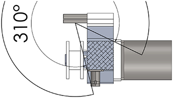
Figure 2. Top-view with a horizontal cut through the tape target system, with indication of the angular range that allows free field of view onto the standard laser-interaction point on the tape.
Download figure:
Standard image High-resolution imageExperiments for this work were conducted in the VEGA-3 laser facility at CLPU. There, the Ti:Sa laser pulse is amplified to an energy  up to 30 J per pulse, and compressed down to a duration
  of 28 fs. After compression, the short laser pulse is transported in high-vacuum of
  mbar to a
  2.5 m off-axis parabola. The focal spot of
  µm full-width at half-maximum is aligned onto the interaction plane, and maintained at constant size for this work. Laser energy and duration per pulse were not constant thorught this study, a controlled variation of these parameters was performed with a laser pulse duration between 28 fs–160 fs and laser pulse energies from 9 J to 28 J. The transport efficiency of the laser line reduces the energy on-target to 82.5% of the pulse energy. With this ranges the system delivers intensities from
  W cm−2 to
  W cm−2. Throughout this work, all given intensities relate to the intensity that would be achieved at the best focus plane. Note that the tape target surface can only be aligned to this plane in the limits of its positioning uncertainty.
The energy on target is extrapolated from calibrations recorded at low-energy, the focal spot at high energy is estimated to be the same as for low-energy measurements. For this experiment, 24% of the energy on target are within in the first Airy disk at low power. The pulse duration is measured on-shot with a second-harmonic autocorrelator system that diagnoses the faint reflection from a thin pellicule positioned between parabola and focus.
Solid-density targets are placed in the laser focus position and tilted by 12.5∘ with respect to the laser axis to avoid reflection back towards laser amplifiers. As the VEGA laser pulse shows no pre-pulses capable of inducing a transparency or breakdown of the target [34], the main acceleration mechanism of charged particles is TNSA [35, 36] with the current laser and target parameters. In TNSA, a population of laser-heated relativistic electrons escapes the target and the successive potential dynamics and electron-refluxing leads to the formation of sheath fields which are capable of accelerating ionized surface contaminants up to several tens of MeV u−1 [37]. A Thomson Parabola spectrometer (TP) with scintillator screen [38] is deployed to discern accelerated ions by energy and charge-to-mass ratio. The spectrometer aims at ions which are accelerated normal to the target surface; the scintillator screen is photographed for every shot and the image is post-processed with the online analysis tool IOSSR [39].
Broad-band EMP are generated by laser-plasma interaction [40]. One source is a space charge field that builds up in the interaction chamber due to laser-driven target discharge [41], between the target at a positive potential and the vacuum-chamber walls at a negative potential. The magnitude and mode structure of electric and magnetic fields depend on the dimensions of the interaction chamber and the seed space charge distribution. Typical cavity resonances at VEGA-3 occupy the band of very high frequencies (VHFs), notably hundreds of MHz [42]. Commercially available calibrated magnetic- and electric-field antennas are used to capture electromagnetic waves inside the interaction chamber: the magnetic-field antenna MDF-9400 (9 kHz–400 MHz, Aaronia AG) and the electric-field antenna OmniLOG-30 800 (300 MHz–8 GHz, AaroniaAG). The MDF-9400 is positioned 30 cm behind the target following the laser axis, and the OmniLOG-30 800 is 30 cm behind the target and 30 cm to the right (in laser direction), both oriented towards the interaction point. The signal is transported via calibrated double shielded SMA cables and through a floating feed-through. Waveforms are captured with an oscilloscope of 2 GHz bandwidth and  sampling rate. The grounding of shields in SMA cables is via the oscilloscope. All EMP signals were corrected for frequency dependent attenuation for all elements of the measurement circuit.
3. Results and discussion
The tape system is capable of forwarding a 9 µm thick aluminium tape by 1.1 cm increments at 0.05 Hz between laser shots at the same frequency every 20 s with  PW in best compression. For this case, the proton cut-off energy in the TNSA spectrum is
  MeV, see figure 3. The shot-to-shot standard deviation of the cut-off energy is 1.5%.
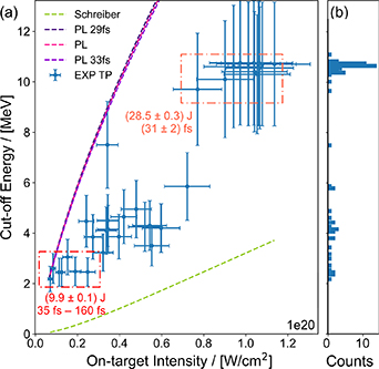
Figure 3. The spectral cut-off energy of accelerated proton beams is recorded for a fixed focal spot size but under variation of laser pulse energy and duration, results for Tape 9-Al-e-K. The uncertainty of the cut-off energy stems from the resolution of the measurement on the detector screen. (a) The cut-off is compared to the modified Schreiber model [43] and the model of Passoni and Lontano (PL) [44]. (b) The histogram shows a narrow peak of  MeV for a burst of 39 shots at 0.05 Hz with comparable laser parameters. Even coarse variations of the laser pulse duration yield comparable cut-off energy when maintaining a constant pulse energy of
  J.
J.
Download figure:
Standard image High-resolution imageThis very small shot-to-shot variation of the proton cut-off energy can be related to the good stability of the laser source parameters (energy and duration) and the on-target intensity affected by the mechanical stability of the tape target system. A theoretical estimate of the uncertainty can be derived from available modelling of the TNSA spectrum, i.e. the analythical form  , where P is a monotonously rising function of the maximum electron energy in the electron cloud. The ratio
  simplifies to
 ![$P/T_\mathrm{e} \approx 4.8 + 0.8 \cdot \text{ln}{[ E_\mathrm{L}^\mathrm{[J]} ]} $](https://content.cld.iop.org/journals/0741-3335/66/4/045003/revision2/ppcfad2690ieqn24.gif) for in-focus laser energies larger than several J [44]. In the relativistic laser regime,
for in-focus laser energies larger than several J [44]. In the relativistic laser regime,  can be assumed to follow the ponderomotive scaling [45] with
  . Here
  is the electron rest mass, c is the speed of light and a0 denotes the normalized vector potential for the laser field. With this set of equations one derives
One calculates  based on the measured
  ,
,  and
and  . The limit drawn by the uncertainty corresponds to the enlargement of the beam radius at 30 µm from the focal plane. Such a de-focusing is consistent with the mechanical fluctuations of the tape target position (compare tape 9-Al-e-K in table 1).
The variation of the proton spectrum is shown in figure 4 since the flux of the proton beam is crucial for many applications. The stability of the spectrum is not as excellent as the stability of the cut-off energy: the high-energy end of the spectrum suffers from variations of the order of 10 s of percent, the low-energy end shows variations comparable to the magnitude. The average spectrum can be described by an exponential two-temperature fit with rate constants  MeV and
  keV. The former compares well with the ponderomotive scaling that results to
  MeV.
MeV.
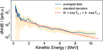
Figure 4. The averaged spectrum of accelerated proton beams is retrieved for shots with  PW at best focus and in best compression for Tape 9-Al-e-K and compared to a two-temperature fit.
Download figure:
Standard image High-resolution imageResults are obtained in a burst with 39 shots, the operation frequency extrapolates to 180 shots per hour. The repetition rate is only limited by the time needed for a mandatory disconnection of the tape controller from the system for the duration of the shot and the successive re-connection. Disconnection was necessary to avoid controller malfunctions caused by the EMP. Future systems with better EMP shielding will reach the full repetition rate of the VEGA system of 1 Hz. Besides this demonstration of maximum performance, studies examined the performance with different types of tape, a method to derive the stability of the operation independent from the measurement of ion spectra and the effect of structured tapes.
3.1. Study of standard tapes: proton acceleration
The size of the ablation hole in standard tapes is known to limit the maximum laser energy on target before rupture occurs [33]. We prevent rupture with a new method that relies on plastified tapes, i.e. we present edge-stabilized tapes.
Figure 3 shows all shots using the 10 mm wide and 9 µm thick aluminium tape that is enforced with Kapton tape
3
on the edges (from now on named Tape 9-Al-e-K). Notably, a mm-thin stripe on each edge is used to smoothen the sliding of the tape over the inner pins and avoid rupture of the tape, see figure 5(a). The adhesion of Kapton is eased with a system of spools that allows quick manufacturing. Results are compared to the modified Schreiber model [43, 46] and to the model of Passoni and Lontano [44] in a wide range of laser pulse energies and durations. Model predictions roughly agree with measured values of the cut-off energy in this intensity regime of  W2 cm−1 to
  W2 cm−1. The Schreiber model underestimates the cut-off energy by a factor of
  . For model calculations, the absorption coefficient does not take into account possible pre-plasma and the electron beam divergence is estimated according to Debayle's model [47] and not measured, both of which might be causes of the discrepancies. The model by Passoni and Lontano overestimates the cut-off by a factor of
  . The model does not take into account material properties of targets and discrepancies might be due to differences in the accelerating potential induced by the respective size of the electron cloud that is influenced by electron scattering.
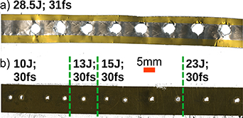
Figure 5. Tape types used during the experiment, respectively scanned after laser shots indicated with their laser pulse parameters. (a) Tape 9-Al-e-K with a mm-thin stripe sticked on each edge, and (b) Tape 89-K-l-ad pure Kapton tape with Silicon Adhesive on the rear side. (a) and (b) have the same scale.
Download figure:
Standard image High-resolution imageTape 9-Al-e-K is compared to a 89 µm thick Kapton tape with thin silicone adhesive on the rear side (from now on named Tape 89-K-l-ad). Tape 89-K-l-ad is shown in figure 5(b), with circular ablation holes for low laser pulse energies and asymmetric shapes for higher energies. For comparable laser parameters, the evaporated volume of Tape 89-K-l-ad is larger than of Tape 9-Al-e-K. Both tapes are compared to a single-shot reference of 9 µm thick aluminium tape which is held by a target matrix. Different to shots on spooled tapes, the single-shot reference is aligned with respect to the laser focus for every shot. Figure 6 shows the proton cut-off energy for the respective shots. The three cases follow the same trend, between types cut-off energies do not vary in the margin of their uncertainty. The largest deviation occurs with a kink to lower cut-off energies for a sequence of shots with intermediate on-target intensities around  W cm−2 for tape 9-Al-e-K, which might be due to a slight systematic miss-alignment. The 89 µm thick Kapton target allows for the same cutoff energy like a 9 µm aluminium target, for highest laser pulse energies in shots at best compression. The mechanisms involved should be part of future work, but the diagnosis of plasma parameters and ion acceleration is beyond the scope of this work. The comparability between aluminium tape and single shot reference is an essential proof of the on-shot alignment stability of the system.
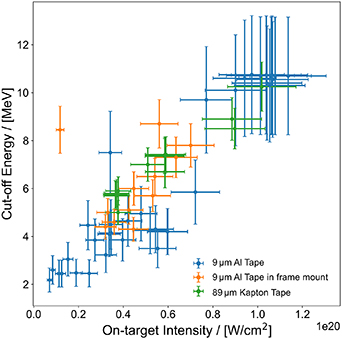
Figure 6. The spectral cut-off energy of accelerated proton beams is recorded for a fixed focal spot size but under variation of laser pulse energy and duration for three types of tape. The uncertainty of the cut-off energy stems from the resolution of the measurement on the detector screen.
Download figure:
Standard image High-resolution image3.2. Online stability
The stability of the cut-off energy of laser accelerated protons is a benchmark for the stability of the proton source. This metric is unavailable in experiments where ion beams are applied to secondary samples. The beam properties are altered by the interaction with samples, e.g. it is not possible to determine the amount of protons which loose all their energy inside the sample and are not transmitted. Here we investigate whether or not the EMP can be used for metrology to monitor the stability in such cases. The magnitude spectrum in the VHF band is sensitive to modifications in the experimental setup [42, 48]. The evolution of the magnetic field amplitude for 39 laser shots at  J pulse energy and
  fs pulse duration on Tape 9-Al-e-K is shown in figure 7. The maximum and minimum amplitude of the time-domain measurement (which are the largest positive and negative oscillation respectively) are stable with small %-level variations around the respective mean values (dashed lines), in accordance to the reproducible TNSA spectrum with a cut-off energy of
  MeV for the same shots (see figure 3). The noise level for this measurements is of the order of 2%–3% of the mean value. The EMP spectrum over the VHF band shows clear peaks in the magnitude spectrum. Their amplitude range is small around the mean value, which points to a reproducible mode structure. Note that the EMP is seeded by the target charging dynamics and space charge deposition. Therefore the magnetic field amplitude and spectrum can depend on the laser parameters, the choice of target material.
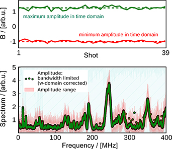
Figure 7. The maximum (largest positive) and minimum (largest negative) magnetic-field amplitude of the time-domain signal (top) and the time integrated average magnitude spectrum (bottom) of 39 shots with  J pulse energy and
  fs pulse duration on Tape 9-Al-e-K.
Download figure:
Standard image High-resolution imageThe signals for all shots of one day with tape 9-Al-e-K are shown in figure 8. Electric and magnetic field amplitudes proof to be sensitive to changes in the laser parameters and miss-alignments of the target system. Note that mechanical shot-to-shot fluctuations and their impact on the laser heated electron dynamics might be neglected for stable target systems. Equation (1) simplifies to  in the regime of the discussed laser energies, such as the variation of the hot electron temperature is of the order of several %.
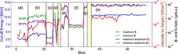
Figure 8. EMP amplitude, proton cut-off energy and laser intensity for shots on Tape 9-Al-e-K. The EMP is shown in terms of the respective absolute values for maximum and minimum magnetic- (B-) and electric- (E-) field amplitudes in the time domain. Amplitudes are normalized to the respective maximum or minimum value of the full shot sequence. Laser pulse energy and pulse duration vary, i.e. (a)  J and 35 fs to 160 fs, (b)–(d)
  J and 30 fs to 65 fs, (e) 10 J to 25 J and 29 fs to 36 fs, (f)
  J, (g)
  J and (h)
  J and
J and  fs. Gaps for intensity in (a) and (f—h) are for unknown pulse durations and (g) shows no cut-off energy due to faulty triggers. No spectrometer traces are observed for (c), (d) and (f) for which the tape got stuck occasionally and shots were fired through holes left by a previous interaction. Yellow boxes are drawn for gaps which are corresponding to shots without laser pulse.
Download figure:
Standard image High-resolution imageAfter shots at (a) 10 J, the amplitudes increase slightly for shots at (b) 15 J. The proton cut-off follows this trend. Blank shots, where the tape got stuck and the laser propagates through the hole produced by previous shots, are visible with (c) minimum time-domain amplitudes. Here also no protons were detected. Shots (d) show fluctuations during an alignment phase of the target position and shots (e) show variations due to the shot-to-shot variation of laser parameters. The low level EMP amplitude for shots (f) with 20 J coincides with a blank ion trace on the ion spectrometer, hinting a miss-alignment of laser or target. Which parts of the beamline were miss-aligned could not be determined after the sequence was concluded. After an alignment check, shots (g)–(h) with  J appear to produce stable cut-off energies and EMP amplitudes. This sequence of shots shows that the EMP can be used as indicator for the quality of the laser-target interaction and successive proton beam characteristics. Future characterisations should aim at a statistical analysis and mapping of EMP amplitudes depending on varying laser parameters and different layouts of the experimental setup.
3.3. Study of modified tapes: debris mitigation
The TaTaS-PW system provides a stable targetry solution, i.e. for proton acceleration. The stability, deduced from cut-off energies of accelerated protons and from EMP spectra, allows for a reliable target supply for laser-solid interactions. Nevertheless, solid targetry produces a large amount of debris due to ablation. Each shot evaporates  mg of aluminium when using a moderate peak-power of
  TW on 9 µm thick tape. Continuous HRR operation at 0.05 Hz would cause debris of 1 kg of aluminium within 22.4 d. We compare the ablation with available modelling in the following and address mitigation strategies, with a study of different tape materials and geometries.
A view on ablation holes in 9 µm thick aluminium is shown in figure 9 for different laser pulse energies at best compression. One notes that the laser punches a hole in the target by means of evaporation. The structure of the tape is weakened and the edges of the ablation zone curl, further increasing the size of the aperture. Thus, for low laser energies, the hole appears elliptical, which may be a matter of projection in the imaging system. For higher laser energies, there are clear deviations from the perfect circular shape. In the following, hole size refers to the size of the ablated zone taking into account curling effects. Hole diameters refer to diameters of circles which interpolate the true ablation zone, equating the respective volumes.
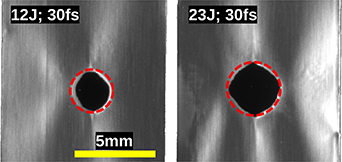
Figure 9. After the laser shot evaporated target material gives way to an ablation hole in the 9 µm thick aluminium tape, (left) for 12 J and (right) for 23 J laser pulse energy at best compression. Dashed lines indicate perfect circles (the circle on the right side is larger than the circle on the left side).
Download figure:
Standard image High-resolution imageAblation holes are compared to a model that predicts sizes of through-holes by assuming that the full heat transferred from the laser-heated electron population to the target drives the evaporation of target material [33] in figure 10. All shots are conducted at best focus, but under variation of laser pulse energy and duration. The laser parameters are shown in terms of laser pulse power and one notes clearly that the power itself does not scale the hole diameter. Theoretical predictions take into account the loss of energetic electrons which depends strongly on laser energy and duration [41]. For shots at best compression the theoretical prediction is in the margin of uncertainty for 92% of the data. The model fails to predict hole diameters for cases where the laser pulse is stretched (i.e. by means of [49]). Note that the error bars for the theoretical prediction stem from the uncertainties of the individual laser pulse parameters, which have been taken into account with dedicated simulations; and for the experimental data error bars come from the precision of measurement of the radius of the holes.
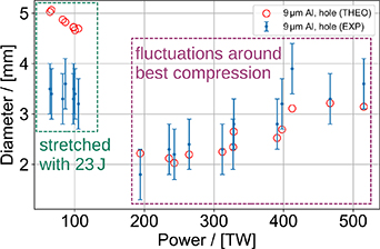
Figure 10. Diameters of the evaporation holes on a 9 µm thick aluminium tape under variation of the laser pulse energy and duration at best focus. Compared are experimental results (EXP) and theoretical predictions (THEO) for two groups of shots: (green) at 23 J laser pulse energy under variation of the duration; and (purple) at best compression varying the laser pulse energy.
Download figure:
Standard image High-resolution imageTwo strategies towards a reduction of debris and the control of the geometry of the ablated area are investigated, (i) with a multi-layer tape to dissipate the heat into a larger volume of low-Z material, and (ii) with micro-structured tapes to limit the region where electrons reflux through matter. Both targets are produced in tape shape and not tested in the tape target system, but pressed in a metal frame in order to allow precise individual alignment with respect to the laser focus.
- (i)The first approach is not successful. Figure 11 shows in comparison to figure 9 that there is no difference to the hole diameter between single- and multi-layer tapes. The amount of ablated aluminium is the same. A 2 mm diameter hole that is drilled in the plastic layer to allow TNSA from the rear surface of the Al appears to be un-altered. The layering may have been not well connected, a challenge that can be addressed with future experiments.
- (ii)As second approach, structured targets proof to be effective for the reduction of debris, see figure 12. The hole diameter in structured tapes remains smaller than the diameter of holes in unstructured tapes. Note that structured tapes are cut in 6 µm thick aluminium, where holes are expected to be larger than for 9 µm thick aluminium as shown in [33]. The structuring reduces the amount of ablated material by 80%. Note that the closest edge of the micro-structure has a distance of 300 µm to the laser interaction point to make sure the TNSA mechanism is not perturbed [50].
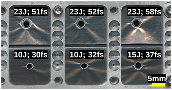
Figure 11. After the laser shot evaporated target material gives way to an ablation hole in the 9 µm thick aluminium tape. The 125 µm thick Mylar layer that was pressed onto the aluminium does not show clear signs of ablation.
Download figure:
Standard image High-resolution image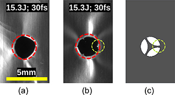
Figure 12. After the laser shot evaporated target material gives way to an ablation hole in (a) the 9 µm thick aluminium tape, and (b) the structured 6 µm thick aluminium tape. The essential difference is the amount of ablated material, (c) which is reduced in structured tapes by cut out (white) zones. Red circles have the same size in (a) and (b). The design of the micro-structure is shown in (c) in comparable orientation to (b). Green circles highlight one arm of the micro structure, remnant after the laser shot in (b).
Download figure:
Standard image High-resolution image
Structuring allows for a precise control of the region in which material ablates. The circular hole in structured tapes remains intact which might prevent rupture of tapes when using thinner stripes of tape of reduced thickness. Such slim tapes are in demand because wide tapes can easily obscure direct lines of sight for side-view diagnostics, e.g. probe beams for plasma and pre-plasma dynamics, particle beam emission or Thomson scattering. Thinner foils are needed to not only access TNSA but also the RPA mechanism for ion acceleration.
4. Conclusions
We successfully implemented a tape target system. This will pave the way for high-repetition-rate experiments of relativistic laser-solid interaction at PW-class laser facilities. As a benchmark, stable ion acceleration via the TNSA mechanism is reported experimentally. We find proton cut-off energies of  MeV for 9 µm thick aluminium targets irradiated by
  W cm−2. The open geometry and modular configuration of the system allows for adaptation to specific experimental setups.
The stability of the system is evaluated in terms of ion spectra and EMP magnitude spectrum. The shot-to-shot standard deviation of the cut-off energy is 1.5% for Kapton reinforced aluminium tapes of 9 µm thickness. The EMP amplitudes in the VHF band in the time-domain provide a novel method to check for the stability of the interaction. The later method will gain importance when ion beams are applied to secondary sources and one can not check the proton spectrum for each shot, or when the production of ions is not the goal of experiments.
The mechanical stability of the tape with respect to the initial alignment position is  µm. This ensures only small fluctuations of the laser intensity on the target as the Rayleigh length of the VEGA-3 focus is approximately 130 µm for this work.
As important aspect for solid targetry which is responsible for much debris, a novel method for debris reduction is introduced. During the typical annual access time at CLPU of 18 weeks, debris of 1 kg could be issued from 9 µm aluminium foil when shot every 20 s for 6 h per day with 400 TW at best focus. With respect to this large amount of debris, we demonstrate a reduction by 80% by introducing micro-structures into the tape.
For future work, the platform will be operated at higher laser intensities, higher repetition rate, and as secondary source for delivery of proton beams at CLPU for studies to reach higher proton energies and a better beam quality.
Acknowledgments
This work would not have been possible without the help of the laser- and the engineering team at CLPU. Special thanks to the workshop of CLPU. This work received funding from the European Union's Horizon 2020 research and innovation program through the European IMPULSE project under Grant Agreement No. 871161 and from LASERLAB-EUROPE V under Grant Agreement No. 871124. It benefited from funding from the Ministerio de Ciencia, Innovación y Universidades in Spain through ICTS Equipment Grant No. EQC2018-005230-P, further from Grant PID2021-125389OA-I00 funded by MCIN/AEI/10.13039/501100011033/FEDER, UE and by 'ERDF A way of making Europe', by the 'European Union' and in addition from grants of the Junta de Castilla y León with Nos. CLP263P20 and CLP087U16. The authors are grateful to I M Vladisavlevici for help in preparing the manuscript.
Data availability statements
No meta data standard yet. The data that support the findings of this study are available upon reasonable request from the authors.
Footnotes
- 3
UHV KAPTON TAPE SILICONE ADHESIVE, seller LewVac, dimensions 12.7 mm width, 0.0889 mm thickness and 32 m length, purchased July of 2020.