(Translated by https://www.hiragana.jp/)
Unpaved Strip Kit

Back to home pageUnpaved Strip Kit

Home > History and Variants > 737 Originals > Unpaved Strip Kit

Contents

Illustrated technical information covering Vol 2 Over 800 multi-choice systems questions Close up photos of internal and external components Illustrated history and description of all variants of 737 Databases and reports of all the major 737 accidents & incidents History and Development of the Boeing 737 - MAX General flightdeck views of each generation of 737's Technical presentations of 737 systems by Chris Brady Detailed tech specs of every series of 737 A collection of my favourite photographs that I have taken of or from the 737 Press reports of orders and deliveries Details about 737 production methods A compilation of links to other sites with useful 737 content Study notes and technical information A compilation of links to major 737 news stories with a downloadable archive A quick concise overview of the pages on this site

spacer

Contents

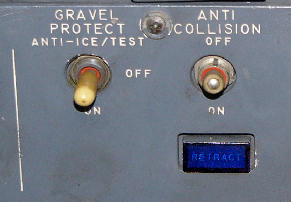
The optional Upaved Strip Kit was made available for the 737-100/200 from Feb 1969. It allowed aircraft to operate from gravel, dirt or grass strips. At its peak of operation, 737s were making over 2000 movements a year from unpaved runways.

Canadian North, one of the last operators of the 737-200 with unpaved strip kits are phasing out their last two of the type by 2022.

See more details about the book

All of the information, photographs & schematics from this website and much more is now available in a 374 page printed book or in electronic format.

*** Updated 05 Aug 2023 ***

The 737 Tech Site on Facebook The 737 Tech Site on Twitter The 737 Tech Site on Instagram

Whatever surface was to be used, certain guidelines had to be observed. The surface had to be smooth with no bumps higher than 3 inches in 100ft; good drainage with no standing water or ruts; and the surface material had to be at least 6 inches thick with no areas of deep loose gravel. Boeing offered a survey service to assess the suitability of potential strips. If a surface was not particularly hard it could still be used by reducing tyre pressure down to a minimum 40psi in accordance with a chart.

Components included:

  • Nose-gear gravel deflector to keep gravel off the underbelly.
  • Smaller deflectors on the oversized main gear to prevent damage to the flaps.
  • Protective metal shields over hydraulic tubing and brake cables on the main gear strut.
  • Protective metal shields over speed brake cables.
  • Glass fibre reinforced underside of the inboard flaps.
  • Metal edge band on elephant ear faring.
  • Abrasion resistant Teflon based paint on wing and fuselage undersurfaces.
  • Strengthened under-fuselage aerials.
  • Retractable anti-collision light.
  • Vortex dissipators fitted to the engine nacelles.
  • Screens in the wheel well to protect components against damage.

The protective equipment listed above means that extra maintenance costs due to tire wear, paint loss, etc is only about $15 per landing (1975 rates).


Vortex Dissipators

Prevent vortices forming at the engine intakes which could cause gravel to be ingested by engine. These consist of a small forward projecting tube which blows pressure regulated (55psi) engine bleed air down and aft from 3 nozzles at the tip to break up the vortices.

The dissipators are operated by a solenoid held switch on the overhead panel which switches off on a squat switch so that climb performance is not affected. (Similar to the wing anti ice switch on 3-900 series).

The GRAVEL PROTECT switch must be on or at the ANTI-ICE/TEST position at any time the engines are running on the ground. Take-offs and landings must be made with the engine bleeds off to ensure that there is sufficient bleed air for their effective operation. Air conditioning may be used with APU bleed air if required.


The GRAVEL PROTECT switch for the anti-vortex jets under the engine nacelles.

The blue caption says RETRACT for the retractable anti-collision light.


Vortex dissipator

This photo shows the airflow patterns in the gravel from the 3 nozzles of the vortex generator.


The nose gear gravel deflector is made of corrosion-resistant steel and has a sheet metal leading edge which acts as an aerofoil to give it aerodynamic stability.

When the gear retracts, the deflector is hydraulically rotated around the underneath of the nose wheel before seating into the faring at the front of the nose wheel well. The rotation is programmed to maintain the deflector in a nose-up attitude during transit. No extra crew action is required to use the deflector and in the event of a manual gear extension, springs and rollers will position it correctly.

The maximum speed for gear operation (V LO) is reduced considerably to 180kts and the max speed with the gear extended (V LE) is only 200kts.

Note that the ground clearance of this nose-gear unit is only 3.5 inches this is enough to allow for flat tyre clearance but care must be taken when crossing runway arrestor cables, particularly try to avoid taxying over the "doughnuts" that support any cables.

The gravel deflector on the nose gear


Operational Procedures
  • Antiskid must be ON for takeoff and landing. (AFM)
  • Vortex dissipators must be ON for takeoff and landing. (AFM)
  • Maximum taxi EPR on gravel: 1.4. (AFM)
  • Gravel Protect switch: ANTI-ICE position when using engine inlet anti-ice. (AFM)
  • Use of rudder pedal steering rather than tiller is recommended to make all turns as large as possible to prevent nose gear from digging in.
  • Thrust to be kept to a minimum to sustain a slow taxy speed.
  • If runway is dusty try to manouvre so that your jet blast does not pick up loose debris that may be blown back over the runway in a crosswind. Dust should be allowed to settle before starting takeoff roll.
  • Notwithstanding the above, use a rolling takeoff wherever possible to avoid debris ingestion when takeoff thrust is set. EPR should be limited to 1.4 or less before brake release.
  • For landings, use of autobrake is recommended.
  • When landing on gravel, use approximately idle reverse, not to exceed 1.8 EPR. Stow reversers by approx 60kts. (AFM)


This extra plate is one of the inboard aft flap gravel protectors.


This tyre screen is to protect vital components from damage if debris is flung into the wheel well from an unpaved strip.

This is a video of the unpaved landing trials narrated by Peter Morton, 737 Marketing; and Lew Wallick, one of the test pilots on the first flight of the 737.
https://www.youtube.com/watch?v=aOpBXmqa0eY

Footer block