Related Resources: calculators
Solid Shaft Equivalent of Hollow Shaft Strength Formula and Calculator
Beam Deflection and Stress Calculators Formulas & Structural Analysis
Strength and Mechanics of Materials Menu
Solid Shaft Equivalent of Hollow Shaft of Same Length Equal Strength Formula and Calculator
Preview Solid Shaft Equivalent of Hollow Shaft of Same Length Equal Strength Calculator
For equal strength in bending, torsion, and/or combined bending and torsion, the diameter of the solid shaft is calculated from the following
When materials of both shafts are same
Eq. 1
D = Do ( 1 - K4 )(1/3)
When materials of shafts are different
Eq. 2
D = Do ( σeh / σes ) ( 1 - K4 )(1/3)
Eq. 3
ratio of inner to outer diameter of hollow shaft
K = Di / Do
Where
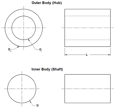
Do = outside diameter of hollow shaft, m (in)
Di = inside diameter of hollow shaft, m (in)
D = diameter of solid shaft , m (in)
K = ratio of inner to outer diameter of hollow shaft
σeh = stress (tensile or compressive) hollow shaft , MPa (psi)
σes = stress (tensile or compressive) solid shaft , MPa (psi)

Figure 1 Hollow and Solid Shaft Dimensions Declarations
References
1. Lingaiah, K., and B. R. Narayana Iyengar, Machine Design Data Handbook, Engineering College Cooperative, Bangalore, India, 1962.
2. Lingaiah, K., and B. R. Narayana Iyengar, Machine Design Data Handbook, Vol. I (SI Units and Customary Metric Units), Suma Publishers, Bangalore, India, 1986.
3. Lingaiah, K., Machine Design Data Handbook, Vol. II (SI Units and Customary Metric Units), Suma Publishers, Bangalore, India, 1986.
4. Soderberg, C. R., ‘‘Working Stresses,’’ J. Appl. Mechanics, Vol. 57, p. A-106, 1935.
5. ASME Code for Design of Transmission Shafting, Standard ANS/ASME B106.1M, 1985.
6. Shigley, J. E., Machine Design, McGraw-Hill Publishing Company, New York, 1956.
7. Kececioglu, D. B., and V. R. Lalli, Reliability Approach to Rotating Component Design, Technical Note TND-7846, NASA, 1975
8. Davies, V. C., H. T. Gough, and H. V. Pollard, Discussion to the Strength of Metals under Combined Alternating stresses, Proc of the Inst. Mech. Eng., 131(3), pp. 66–69, 1935.
9. Loewenthal, S. H., Proposed Design Procedure for Transmission Shafting under Fatigue Loading, Technical Note TM-7802, NASA, 1978.
10. Gough, H. J., and H. V. Pollard, The Strength of Metals under Combined Alternating stresses, Proc of the Inst. Mech. Eng., 131(3), pp. 3–103, 1935.
Related
- Diameter Combined Torsion and Bending Equation and Calculator
- Solid Shaft with Simple Bending Diameter Equation and Calculator
- Circular Shaft Opposite Sides flattened Torsional Deformation Stress Equation and Calculator
- Static Loading Shaft or Axle Analysis Formula and Calculator
- Shaft Torsional Deflection and Rigidity Formulae and Calculator
- Cross Shaft Torsional Deflection, Stress Equation and Calculator
- Torsional Stiffness Hollow Shaft Equations and Calculator
- Shaft Torsion Stress Calculator and Equations
- Torsional Deflection of Shaft
- Section Modulus, Radii of Gyration Circular, Eccentric Shape Equations
- Round Structural Tube Per. ASTM 1085, Hollow Structural Section Round Structural Tube
- Curved Circular Beam Stress