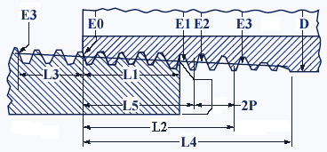
National Standard Taper Pipe Threads Size NPT Chart
Standard ANSI Hardware
Manufacturing
Processes
Applications
and Design
National Standard Taper Pipe Threads Size NPT Chart - Includes both External and internal Pipe Thread Data. The taper rate for all NPT threads is 1⁄16 (3⁄4 inch per foot) measured by the change of diameter (of the pipe thread) over distance. The angle between the taper and the center axis of the pipe is 1° 47'′ 24"″ (1.7899°). Commonly-used sizes are 1/⁄8, 1/⁄4, 3/⁄8, 1⁄/2, 3⁄/4, 1, 1 1⁄/4, 1 1⁄/2, and 2 inch, appearing on pipes and fittings by most U.S. suppliers. Sizes smaller than 1/⁄8 inch are occasionally used for compressed air, while sizes larger than 2 inches are uncommon, due to the use of alternative methods of joining that are used with these larger sizes. NPT is defined by ANSI/ASME standard B1.20.1.
Nominal Pipe Size is loosely related to the inside diameter of Schedule 40 pipe. Because of the pipe wall thickness, the actual diameter of the threads is larger than the NPS, considerably so for small NPS. Other schedules of pipe have different wall thickness but the OD (outer diameter) and thread profile remain the same, so the inside diameter of the pipe is therefore different from the nominal diameter.
Related:
- Basic Dimensions, American National Standard Taper Pipe Threads, NPT
- Pitch Diameter Formulas and Calculator NPT American National Standard Taper Pipe Threads
|
Notes: Reference ANSI/ASME B1.20.1-1983 (R1992) All units are in inches. |
 |
|
Outside Diameter D |
Nominal Pipe Size |
Threads per Inch (Pitch) |
Thread Pitch Length, P |
Pitch Diameter at External Thread Start E0 |
Hand Tight Thread Engagement
Length, L1 |
Diameter E1 |
Maximum Thread Engagement L2
|
Diameter E2 |
|
0.3125 |
1⁄16 |
27 |
0.03704 |
0.27118 |
0.160 |
0.28118 |
0.2611 |
0.28750 |
|
0.405 |
1⁄8 |
27 |
0.03704 |
0.36351 |
0.1615 |
0.37360 |
0.2639 |
0.38000 |
|
0.540 |
1⁄4 |
18 |
0.05556 |
0.47739 |
0.2278 |
0.49163 |
0.4018 |
0.50250 |
|
0.675 |
3⁄8 |
18 |
0.05556 |
0.61201 |
0.240 |
0.62701 |
0.4078 |
0.63750 |
|
0.840 |
1⁄2 |
14 |
0.07143 |
0.75843 |
0.320 |
0.77843 |
0.5337 |
0.79179 |
|
1.050 |
3⁄4 |
14 |
0.07143 |
0.96768 |
0.339 |
0.98887 |
0.5457 |
1.00179 |
|
1.315 |
1 |
11 1⁄2 |
0.08696 |
1.21363 |
0.400 |
1.23863 |
0.6828 |
1.25630 |
|
1.660 |
1 1⁄4 |
11 1⁄2 |
0.08696 |
1.55713 |
0.420 |
1.58338 |
0.7068 |
1.60130 |
|
1.900 |
1 1⁄2 |
11 1⁄2 |
0.08696 |
1.79609 |
0.420 |
1.82234 |
0.7235 |
1.84130 |
|
2.375 |
2 |
11 1⁄2 |
0.08696 |
2.26902 |
0.436 |
2.29627 |
0.7565 |
2.31630 |
|
2.875 |
2 1⁄2 |
8 |
0.12500 |
2.71953 |
0.682 |
2.76216 |
1.1375 |
2.79062 |
|
3.500 |
3 |
8 |
0.12500 |
3.34062 |
0.766 |
3.38850 |
1.2000 |
3.41562 |
|
4.000 |
3 1⁄2 |
8 |
0.12500 |
3.83750 |
0.821 |
3.88881 |
1.2500 |
3.91562 |
|
4.500 |
4 |
8 |
0.12500 |
4.33438 |
0.844 |
4.38712 |
1.3000 |
4.41562 |
|
5.563 |
5 |
8 |
0.12500 |
5.39073 |
0.937 |
5.44929 |
1.4063 |
5.47862 |
|
6.625 |
6 |
8 |
0.12500 |
6.44609 |
0.958 |
6.50597 |
1.5125 |
6.54062 |
|
8.625 |
8 |
8 |
0.12500 |
8.43359 |
1.063 |
8.50003 |
1.7125 |
8.54062 |
|
10.750 |
10 |
8 |
0.12500 |
10.54531 |
1.210 |
10.62094 |
1.9250 |
10.66562 |
|
12.750 |
12 |
8 |
0.12500 |
12.53281 |
1.360 |
12.61781 |
2.1250 |
12.66562 |
|
14.000 |
14 |
8 |
0.12500 |
13.77500 |
1.562 |
13.87262 |
2.2500 |
13.91562 |
|
16.000 |
16 |
8 |
0.12500 |
15.76250 |
1.812 |
15.87575 |
2.4500 |
15.91562 |
|
18.000 |
18 |
8 |
0.12500 |
17.75000 |
2.000 |
17.87500 |
2.6500 |
17.91562 |
|
20.000 |
20 |
8 |
0.12500 |
19.73750 |
2.125 |
19.87031 |
2.8500 |
19.91562 |
|
24.000 |
24 |
8 |
0.12500 |
23.71250 |
2.375 |
23.86094 |
3.2500 |
23.91562 |
Related
- Straight Pipe Threads Table Chart ANSI
- Pipe Thread Tap and Drill Size Chart ANSI NPT
- External Pipe Thread Design, Specifications and NPT Pipe Thread Tolerances
- Pipe Thread Pitch Diameter Formulas and Calculator
- External British Pipe Threads (Whitworth Form) Table per. BS EN ISO 228
- Pipe Thread Installation Torque Table Chart
- Internal Dryseal Pipe Thread Tap Drill Sizes Recommendations
- Whitworth BS Pipe Thread Size and Tap Drill Table Chart DIN/ISO 228